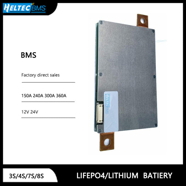
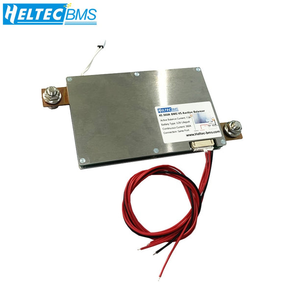
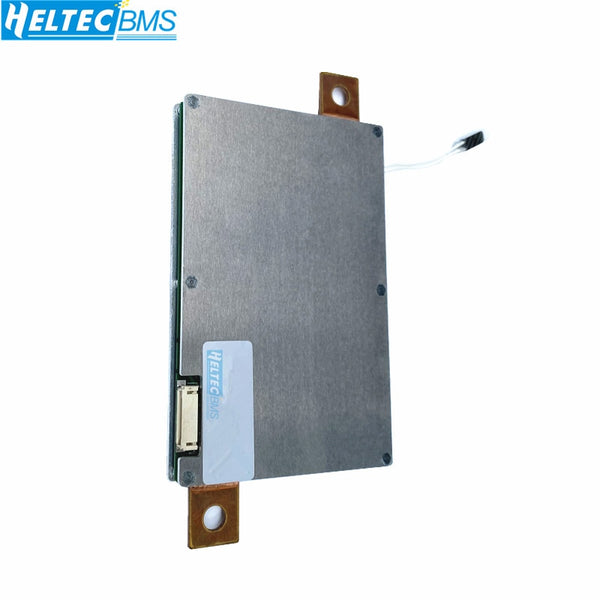
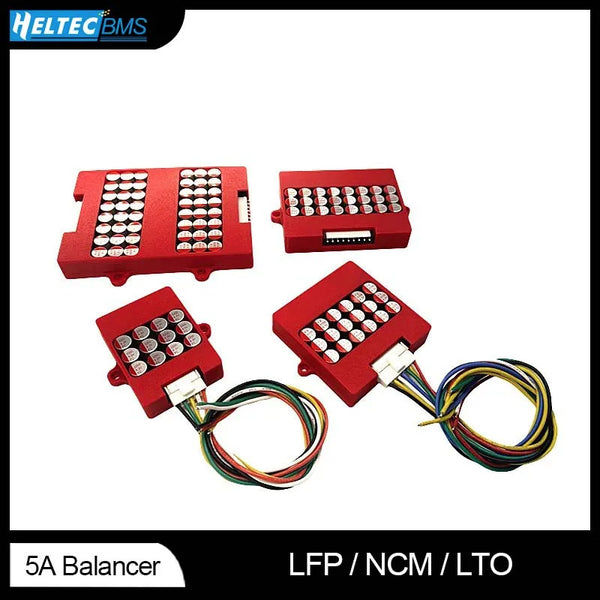
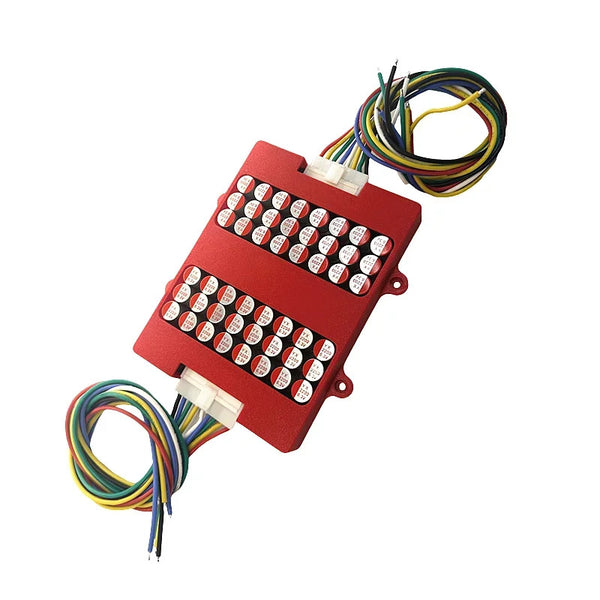
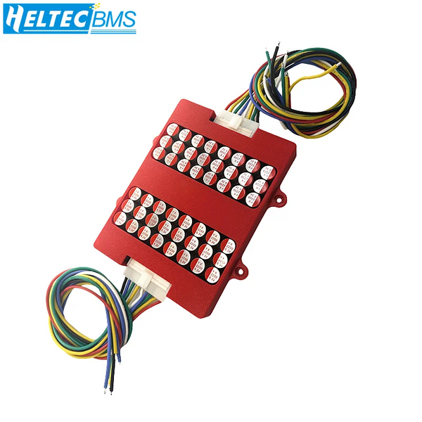
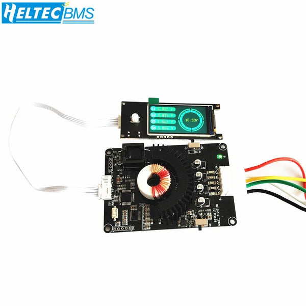
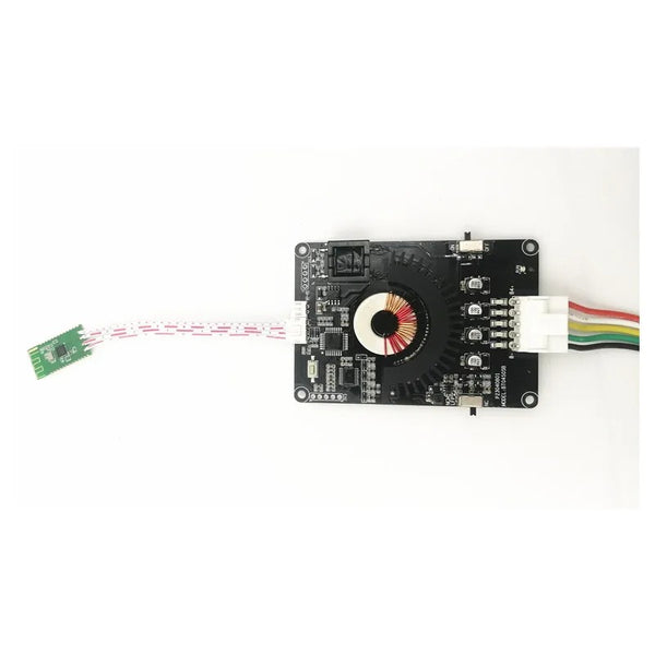
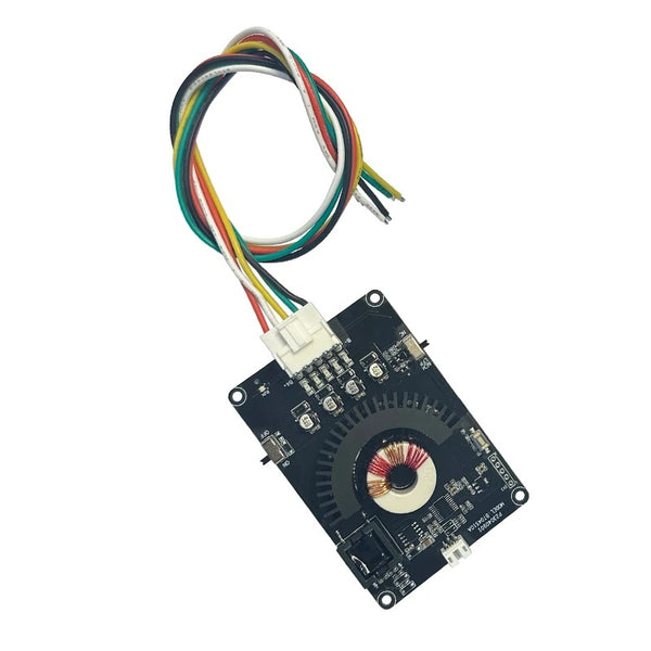
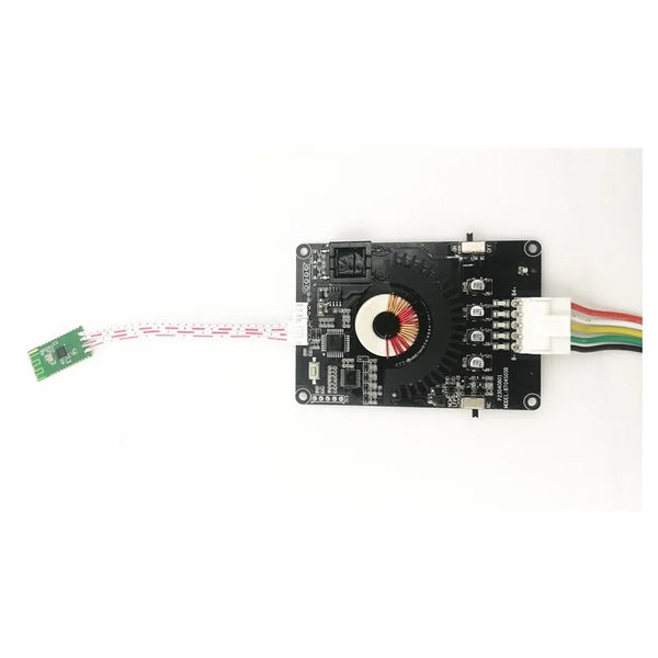
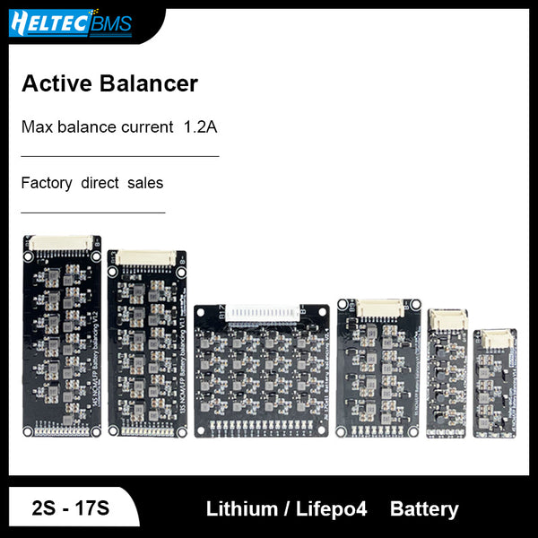
3S 4S 7S 8S 12V 24V BMS 1.5A Active Equalizer Balancer continuous 150A 240A 300A 360A Lifepo4/ Lithium Battery protection board
Feture 1. Imported new packaged SMD MOS: 50% wider. The internal resistance is 5 times lower and the diversion is 5 times higher.60% thinner, 3 times faster heat dissipation + double-sided two-layer heat dissipation design 6 times+2. The ultra-wide and thick T2 pure copper bar allows the current to last...

Feture
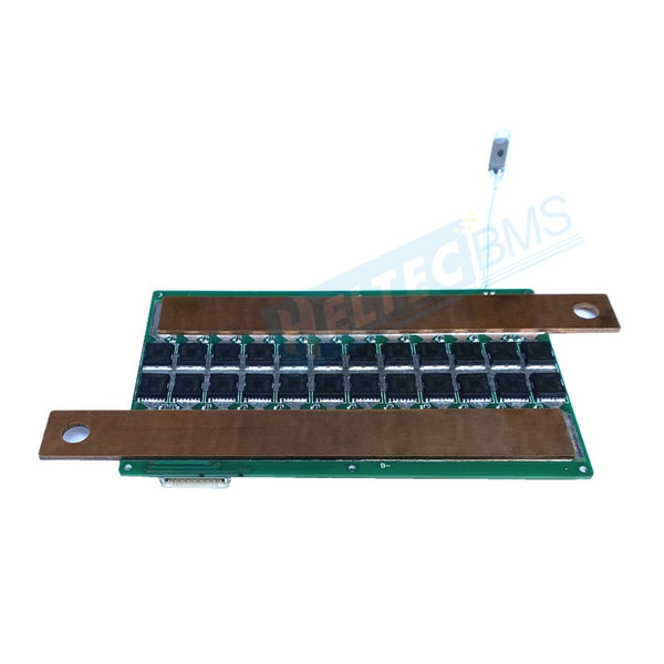
1. Imported new packaged SMD MOS: 50% wider. The internal resistance is 5 times lower and the diversion is 5 times higher.60% thinner, 3 times faster heat dissipation + double-sided two-layer heat dissipation design 6 times+
2. The ultra-wide and thick T2 pure copper bar allows the current to last 500A without heating up, and each chip has a unified current. The wave shunt insurance design makes the use and safety of each chip better.
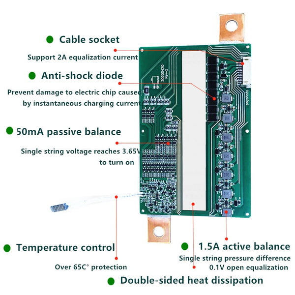
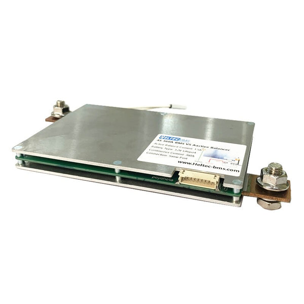
3. Cable socket :Support 2A equalization current
4. Anti-shock diode:Prevent damage to electric chip caused by instantaneous charging current
5. 50mA passive balance:Single string voltage reaches 3.65V to turn on
6. Temperature control:Over 65C° protection
7. Double-sided heat dissipation
8. 1.5A active balance:Single string pressure difference 0.1V open equalization


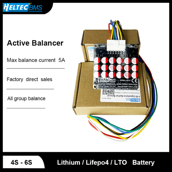
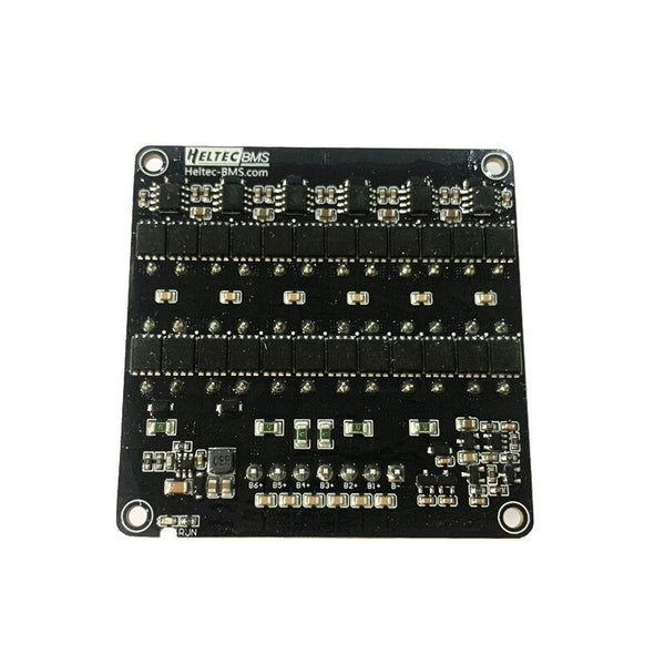
Introduction of Active Balance Protection Board
Balance method: Energy transfer, two adjacent battery cells, high-voltage batteries charge low-voltage batteries
Typical balance current: 1.5A
Applicable batteries: ternary or iron-lithium batteries with battery cell voltage in the range of 2.8-4.5V, mainly
Applicable to 2 to 8 strings, multiple strings with large capacity, and the battery cell voltage is easy to produce pressure difference after long-term use
Balanced battery pack.
Balanced starting working conditions: Meet the following two conditions at any time:
1. The voltage of each single battery cell works at: minimum 2.8+0.1v, maximum 5.0V+0.1V.
2. When the pressure difference between two adjacent cells is greater than 100m±30mV, the equalization is started.
Equalization current description: The greater the pressure difference, the equalization current will increase correspondingly, the maximum equalization
The current is 1.5A.

Installation Notes:
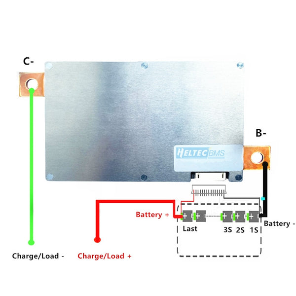
1. First connect the B-line to the battery negative terminal (B-line, fixed thick short wire) and then connect the flat cable (before connecting the flat cable, be sure to unplug the flat cable from the board).
2. Start wiring from BCO, connect BC0 to the total negative electrode of the battery, the second cable BC1 connects to the positive electrode of the first string of batteries, the third cable BC2 connects to the anode of the second string of batteries, and the fourth cable BC3 to the third string of batteries Positive.... and so on.
3. After connecting the cable, measure the voltage between each two adjacent cables from the header. The voltage of the polymer battery should be less than 4.22V, and the voltage of the iron-lithium battery should be less than 3.65V. Insert the cable after checking.
4. Connect the negative pole of the charger and the negative pole of the load to C-. The cable connection method has nothing to do with the color, only the correct order is required.
5. Finally, measure whether the total voltage of the battery is equal to the output voltage of the protection board, and the protection board works normally if it is equal. If they are not equal, you can first check whether the wrong wire is connected, whether the single string voltage is in normal state, whether the series connection is in good contact, and then recharge and activate, or short-circuit B-/C-5 seconds, or re-plug the cable.
Basic requirements before lithium battery pack assembly:
1. First test the inner anode of the single cell. 2. Test the capacity of the monomer. 3. Choose a battery with the same internal resistance and capacity, charge it to full voltage and then assemble it.
The working principle of the protection circuit of lithium battery:
When the voltage of a string of cells is too high, it will be completely unable to be charged, and a string of cells will be powered off if the voltage is too low.


